.
http://hertaville.com/2012/07/28/stm32f0-gpio-tutorial-part-1/ ++++++++++++
http://blog.mark-stevens.co.uk/2013/03/rediscovering-the-stm32-discovery-board/
http://blog.mark-stevens.co.uk/2013/03/stm32-simple-gpio-and-some-flashing-leds/
http://www.embedds.com/programming-stm32f10x-io-port-pins/
http://eliaselectronics.com/stm32f4-tutorials/stm32f4-gpio-tutorial/
.
In order to understand how to write own programs we need to get to some basics…
best place to start is input and output system (I/O).
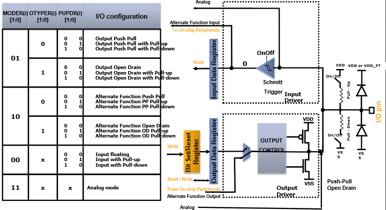
Port pins are able to work in several modes:
- Input floating;
- Input pull-up;
- Input pull-down;
- Analog;
- Output open drain;
- Output push-pull;
- Alternate function push-pull;
- Alternate function open drain.
Pins are organized as 16 bit ports that have their names like PORTA, PORTB, PORC, PORTD…
Ports are controlled with 32-bit words.
General Purpose Input/Output
– Driver : stm32f4xx_gpio :
-> stm32f4xx_gpio.h
-> stm32f4xx_gpio.c
The STM32F407 microcontroller on the STM32F4 Discovery board has 9 general purpose input/output (GPIO) ports named Port A, B, C, D, E, F, G, H and I. Each port can have up to 16 pins, exept port I only 12 pins.
stm32f4xx.h :
/*!< Peripheral base address in the alias region */
#define PERIPH_BASE ((uint32_t)0x40000000)
.
/*!< Peripheral memory map */
#define APB1PERIPH_BASE PERIPH_BASE
#define APB2PERIPH_BASE (PERIPH_BASE + 0x00010000)
#define AHB1PERIPH_BASE (PERIPH_BASE + 0x00020000)
#define AHB2PERIPH_BASE (PERIPH_BASE + 0x10000000)
.
/*!< AHB1 peripherals */
#define GPIOA_BASE (AHB1PERIPH_BASE + 0x0000)
#define GPIOB_BASE (AHB1PERIPH_BASE + 0x0400)
#define GPIOC_BASE (AHB1PERIPH_BASE + 0x0800)
#define GPIOD_BASE (AHB1PERIPH_BASE + 0x0C00)
#define GPIOE_BASE (AHB1PERIPH_BASE + 0x1000)
#define GPIOF_BASE (AHB1PERIPH_BASE + 0x1400)
#define GPIOG_BASE (AHB1PERIPH_BASE + 0x1800)
#define GPIOH_BASE (AHB1PERIPH_BASE + 0x1C00)
#define GPIOI_BASE (AHB1PERIPH_BASE + 0x2000)
.
I/O port control registers
Each port has associated with it the following set of registers:
- GPIO port mode register (GPIOx_MODER)
- GPIO port output type register (GPIOx_OTYPER)
- GPIO port output speed register (GPIOx_OSPEEDR)
- GPIO port pull-up/pull-down register (GPIOx_PUPDR)
- GPIO port input data register (GPIOx _IDR)
- GPIO port outp ut data register (GPIOx_ODR)
- GPIO port bit set/reset register (GPIOx _BSRR)
- GPIO port configuration lock register (GPIOx_LCKR)
- GPIO alternate function low register (GPI Ox_AFRL)
- GPIO alternate function high register (GPIOx_AFRH)
- GPIO Port bit reset register (GPIOx_BRR)
stm32f4xx.h :
typedef struct
{
__IO uint32_t MODER; /*!< GPIO port mode register, Address offset: 0x00 */
__IO uint32_t OTYPER; /*!< GPIO port output type register, Address offset: 0x04 */
__IO uint32_t OSPEEDR; /*!< GPIO port output speed register, Address offset: 0x08 */
__IO uint32_t PUPDR; /*!< GPIO port pull-up/pull-down register, Address offset: 0x0C */
__IO uint32_t IDR; /*!< GPIO port input data register, Address offset: 0x10 */
__IO uint32_t ODR; /*!< GPIO port output data register, Address offset: 0x14 */
__IO uint16_t BSRRL; /*!< GPIO port bit set/reset low register,Address offset: 0x18 */
__IO uint16_t BSRRH; /*!< GPIO port bit set/reset high register,Address offset: 0x1A */
__IO uint32_t LCKR; /*!< GPIO port configuration lock register, Address offset: 0x1C */
__IO uint32_t AFR[2]; /*!< GPIO alternate function registers, Address offset: 0x20-0x24 */
} GPIO_TypeDef;
Control Registers
The GPIOx_MODER register is used to select the I/O direction (input, output, AF, analog).
The GPIOx_OTYPER register is used to select the output type (pushpull or open-drain)
The GPIOx_OSPEEDR register is used to select speed
GPIOx_OSPEEDR register bits whatever the I/O direction).
The GPIOx_PUPDR register is used to select the pull-up/pull-down whatever the I/O direction.
typedef struct
{
uint32_t GPIO_Pin; /* Specifies the GPIO pins to be configured.
This parameter can be any value of @ref GPIO_pins_define */
GPIOMode_TypeDef GPIO_Mode; /* Specifies the operating mode for the selected pins.
This parameter can be a value of @ref GPIOMode_TypeDef */
GPIOSpeed_TypeDef GPIO_Speed; /* Specifies the speed for the selected pins.
This parameter can be a value of @ref GPIOSpeed_TypeDef */
GPIOOType_TypeDef GPIO_OType; /* Specifies the operating output type for the selected pins.
This parameter can be a value of @ref GPIOOType_TypeDef */
GPIOPuPd_TypeDef GPIO_PuPd; /* Specifies the operating Pull-up/Pull down for the selected pins.
This parameter can be a value of @ref GPIOPuPd_TypeDef */
} GPIO_InitTypeDef;
– GPIO_Pin • Específica o pino GPIO a ser configurado
– GPIO_Mode • Específica o modo de operação do pino GPIO
– GPIO_Speed • Específica a velocidade do pino GPIO
– GPIO_OType • Específica o tipo de operação de um pino GPIO quando configurado como saída
– GPIO_PuPd • Específica se o pino é ligado em modo Pull-up/Pull-donw
Bit Set/Reset Register (BSRR)
BSSR register has been split into two components BSSRL and BSSRH.
/* BSRRL refer to bits 0-15 of BSRR which set the corresponding bit of the port bits 0 – 15 of a port */
/* BSRRH refer to bits 16-31 of BSRR which reset the corresponding bit of the port bits 0 – 15 of a port */
GPIOD->BSRRL = 0x00001000;
GPIOD->BSRRH = 0x00001000;
GPIOx_IDR and GPIOx_ODR
Every GPIO port has an input and output data register, ODR and IDR respectively, which hold the status of the pin
Input and output data registers .
GPIOx_ODR stores the data to be output, it is read/write accessible.
The data input through the I/O are stored into the input data register (GPIOx_IDR), a read-only register.
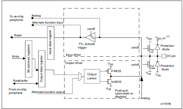
Basic structure of a five-volt tolerant I/O port bit :
STM32 I/Os are 5V tolerant. Anyway proper design should use 5 to 3.3V level converters.
GPIO Functions
GPIO functions are defined @ stm32f4xx_gpio.c
Init / Config
–GPIO_DeInit • Reinicializa os registos do periférico GPIO para o seu valor por defeito ( valor de reset ) ;
–GPIO_Init • Inicializa o periférico GPIO com os parâmetros da estrutura de configuração (GPIO_InitStruct);
–GPIO_StructInit • Inicializaca da um dos campos da estrutura de configuraçãodo GPIO com valores pordefeito;
–GPIO_PinLockConfig • Bloqueia os registos de configuração de um pino GPIO;
Read / Write
–GPIO_ReadInputDataBit • Lê o valor de um pino de entrada (input) GPIO
–GPIO_ReadInputData • Lê o valor de um porto de entrada (input) GPIO
–GPIO_ReadOutputDataBit • Lê o valor de um pino de saída (output) GPIO
–GPIO_ReadOutputData • Lê o valor de um porto de saída (output) GPIO
–GPIO_SetBits • Ativa os pinos específicos de um porto GPIO
–GPIO_ResetBits • Desativa os pinos específicos de um porto GPIO
–GPIO_WriteBit • Escreve o valor pretendidos num determinado pino GPIO
–GPIO_Write • Escreve os dados pretendidos num determinado porto GPIO
–GPIO_ToggleBits • Inverte o valor dos pinos específicos de um porto GPIO
Code
#include <stm32f4xx.h>
/* This TypeDef is a structure defined in the ST’s library and it contains all the properties
the corresponding peripheral has, such as output mode, pullup/ pulldown resistors etc. */
GPIO_InitTypeDef GPIO_InitStruct;
/* This enables the peripheral clock to the GPIOD IO module, Every peripheral’s clock has to be enabled .
The STM32F4 Discovery’s User Manual and the STM32F407VGT6’s
datasheet contain the information which peripheral clock has to be used.*/
/* stm32f4xx_rcc.c have to be included in the project */
RCC_AHB1PeriphClockCmd (RCC_AHB1Periph_GPIOD, ENABLE);
/* In this block of instructions all the properties of the peripheral, the GPIO port in this case,
are filled with actual information and then given to the Initfunction which takes care of the low level stuff
(setting the correct bits in the peripheral’s control register)*/
GPIO_InitStruct.GPIO_Pin= GPIO_Pin_13; // we want to configure LED3 GPIO pin
GPIO_InitStruct.GPIO_Mode= GPIO_Mode_OUT; // we want the pins to be an output
GPIO_InitStruct.GPIO_Speed= GPIO_Speed_50MHz; // this sets the GPIO modules clock speed
GPIO_InitStruct.GPIO_OType= GPIO_OType_PP; // this sets the pin type to push / pull (as opposed to open drain)
GPIO_InitStruct.GPIO_PuPd= GPIO_PuPd_NOPULL; // this sets the pullup/ pulldownresistors to be inactive)
// this finally passes all the values to the GPIO_Initfunction which takes care of setting the corresponding bits.
GPIO_Init(GPIOD, &GPIO_InitStruct);
//sets GPIOD pin13 (stm32f4discovery LED3)
GPIO_SetBits(GPIOD,GPIO_Pin_13);
.
.
.
.
.
.
.


