Boundary Scan
look also in this blog https://bluetechs.wordpress.com/zothers/x/jtag/
Boundary_Scan_Tutorial_Asset ( PDF File )
.
Equipment
http://www.tek.com/ Tektronix
www.scope-of-the-art.com/ad/emi Rhode & SCHWARZ , analyze EMI problems
.
Digital and analog analyser
.
470 $
Red Pitaya is an open-source measurement and control tool replacing many expensive laboratory instruments
.
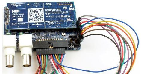
LabTool
Recently I bought this logic analyser by 100$, from embedded artists.
That´s why I made this more detailed desription,
http://www.embeddedartists.com/products/app/labtool.php
Manual [PDF file] : Manual LabTool_UsersGuide_revPA5
Schematic [PDF file] : Schematic LabTool_revB
.
11 channel logic analyzer
2 channel oscilloscope
11 channel digital signal generator
2 channel analog signal generator
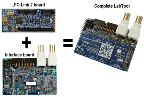
The hardware is built around the LPC4370 microcontroller, which is found on the LPC-Link 2 board.
The hardware is the combination of an interface board and the LPC-Link 2 board that is mounted on this interface board, see picture below.
The user interface for LabTool is software running on a PC. Communication between the hardware
and the pc take place over a High-Speed (480 Mbps) USB2.0 link.
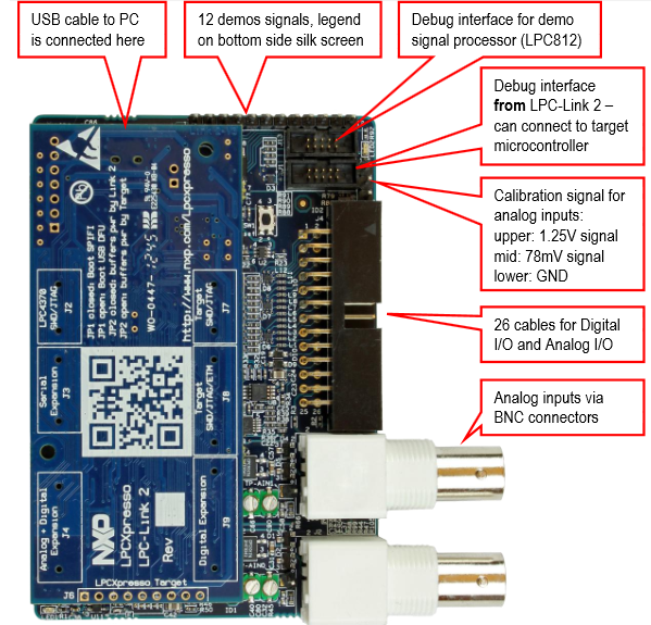
As an extra bonus, there are 12 demonstration signals generated by an on board microcontroller.
These are UART, I2C, SPI, PWM and binary counter signals, easily available on 100 mil pitch pinheader.
The signals can be used to learn how to make full use of the LabTool logic analyzer features and how to work with a logic analyzer in general.
The signals can be used to learn how to make full use of the LabTool logic analyzer features and how to work with a logic analyzer in general.
The LPC-Link 2 is a debug interface (Cortex debug) and even though the LPC-Link 2 is mounted in the interface board, creating the LabTool, the Cortex debug interface is available and can be used, see picture below.
.
.
.
.
.
.
.
.
.
.
.
.
.
.
.
.
.
.
.
.
.
.
.
.
.


