Types of interruption :
Traps Interruption by software
Interruptions External Interruption by hardware :
Exceptions Internal Interruption by hardware
The exceptions are thrown due to problems in the implementation of the current code segment,
due to hardware limitations or characteristics :
Memory fault
Hardware fault
Division by zero
Interruptions Controller
– Usado para recolher os sinais de interrupção recebidos de várias fontes de interrupção e enviá-los para o processador;
– Tipos Controladores:
• Não-vetorizado (MIPS);
• Vectorizado (x86,8051,Cortex-M4);
STM32F407VG
–82 interrupções : 82 de prioridade configurável;
–10 excepções: 3 de prioridade fixa , 7 de prioridade configurável;
Driver :
– startup_stm32f4xx (startup_stm32f4xx.h, startup_stm32f4xx.c) :
boot code (arranque) of the processor.
– stm32f4xx_it : definition code of interrupts
– Misc (misc.h, misc.c ) : Miscellaneous Driver (API NVIC)
The situation where the execution of the regular program is suspended and the processor is forced to take care of the important event is called an interrupt. Such situation is initiated by an electrical signal called interrupt request. The interrupt request can be issued by a hardware built into the microcontroller, but can also be issued by an external hardware connected to a pin of a port.
The example below will show how to program a microcontroller to respond to the interrupt request caused by pressing a pushbutton connected to port E, bit 3.
A special block of hardware is built into the microcontroller in order to release the processor from complex tasks involved in handling interrupt requests. This hardware is called interrupt controller. The interrupt controller hardware is capable of receiving an interrupt request signal, interpreting it as a justified reason to stop the processor from executing the regular program and actually forcing the processor to jump to and execute a special piece of code called interrupt function. It is the task of the processor to return to the regular program after the execution of the interrupt function and continue its execution as if nothing has happened.
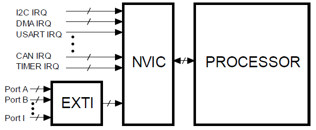
In STM32F4xx series microcontrollers the interrupt controller is called Nested Vectored Interrupt Controller (NVIC). The controller NVIC can handle interrupt requests caused by most hardware (like DMA requests, interrupt requests from communication channels USART, CAN, I2C, and timers) built into the microcontroller alone, and also receives interrupt requests from ports through an additional hardware called External interrupt/event Controller (EXTI). A simplified block diagram for the processing of interrupt request signals in shown in Figure :
.
In order to utilize the interrupt capabilities of the microcontroller the following must be fulfilled:
The interrupt function must be prepared.
This means that the programmer must know what to do in case of an interrupt request, and must write the code (interrupt function) to be executed due to the interrupt. The interrupt function must be written in a special way not to harm the execution of the regular program and the compiler must be notified that this is the function to be executed in case of a certain interrupt request on a certain event. The interrupt function cannot receive or return any arguments; the arguments used within the interrupt function must be declared as global at the beginning of the regular program.
The interrupt controller NVIC must be initialized and enabled.
Since changing of the settings within the interrupt controller is a delicate task and the registers involved into initialization of this controller can be accessed only from a privileged state of the processor, a set of functions to change/initialize the controller NVIC is included in a library within the compiler package. Each function from the set will be explained below.
The controller EXTI must be initialized and enabled
to sort-out the signals at ports and interpret them as interrupt requests. The procedure is completed by writing bits in registers in a normal fashion.
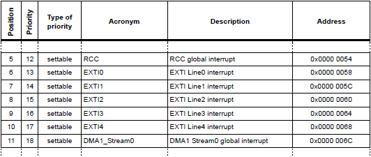
Once the controller NVIC receives the interrupt request it validates it and notifies the processor. The processor then requests the code of the interrupt request source and uses it to find the pointer to the corresponding interrupt function from the interrupt vector table. The table is located in the memory of the microcontroller, and has more than 80 entries for vectors. The complete listing of vectors is given in ST document RM0090.pdf. The default priority for interrupts is given in column 2 of the same table, but the priority can be changed by the software. From this table one can see that there are seven vectors reserved for interrupt requests from ports; these vectors are named EXTIx, where x stands for the number. These seven vectors can serve 16 interrupt requests issued through ports; some vectors are shared by more than one interrupt request.
The vector table itself as used by the compiler can be seen in assembly language source file “startup_stm32f4xx.s”
Individual vectors to point to corresponding interrupt functions are placed into this table during the compilation process, and the functions to be executed on individual interrupt requests must have the same names as stated in this table. As an example, the interrupt function to be executed on external interrupt EXTI3 must have the name “EXTI3_IRQHandler”. The required names of interrupt functions for other interrupt request can be obtained from this vector table.
As stated before the controller NVIC can be handled only in privileged mode, and a set of functions to change registers of the controller is available to ease the setting of the controller. The functions available are:
– NVIC_EnableIRQ (IRQ#)
Enables the handling for the given interrupt request (IRQ#) as specified in Table in ST document RM0090.pdf.
The number IRQ# can also be replaced by a human-friendly definition from file »stm32f4xx.h«.
– NVIC_DisableIRQ (IRQ#)
Disables the handling for the given interrupt request (IRQ#).
– NVIC_SetPendingIRQ (IRQ#)
Sets the status of an interrupt request as pending.
– NVIC_ClearPendingIRQ (IRQ#)
Clears the status of an interrupt request from being pending.
– NVIC_GetPendingIRQ (IRQ#): Inquires about the pending status of a given interrupt request (IRQ#) and returns a non-zero value if IRQ# is pending.
– NVIC_SetPriority (IRQ#, priority#)
Sets the priority for the given interrupt request (IRQ#) with configurable priority level to value stated by priority#.
– NVIC_GetPriority (IRQ#)
Reads the priority for the given interrupt request with configurable priority level.
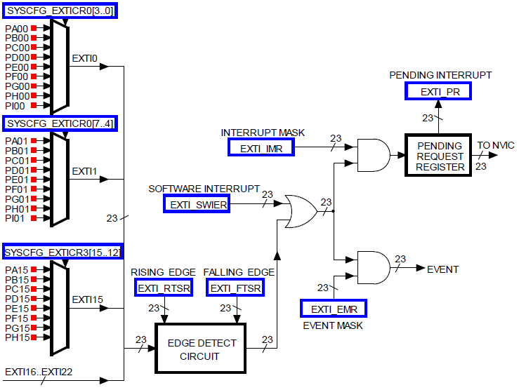
The controller EXTI handles the processing of interrupt request signals from all bits of ports (144 of them) and concentrates the requests into 16 (23 including some extra interrupt request sources, see RM0090.pdf for details) lines to be passed on to controller NVIC. It consists of 16 multiplexers for routing signals from ports and hardware to evaluate the routed interrupt request signals, see figure :
The hardware of controller EXTI : blue boxes are registers, red dots are input pins
Multiplexers are used concentrate interrupt request signals into fewer. Bits 0 from all ports enter a multiplexer, and one of them can be used as an EXTI0 interrupt request signal. The multiplexer is controlled by four least significant bits of register SYSCFG_EXTICR[0]; combination ‘0010’ for instance selects PC00. Bits 1 from all ports enter next multiplexer, and one of them can be used as an EXTI1 interrupt request signal. The multiplexer is controlled by next four bits of register SYSCFG_EXTICR[0]. The same pattern repeats for other bits. Note that the SYSCFG_EXTICR[x] registers reside in SYSCFG block which must be clocked in order to be used.
The resulting bus is 23-bits wide and enters a circuit for edge detection; an interrupt can be issued on rising and/or falling edge of a signal, and the appropriate edge for each of the 23 signals is enabled individually by setting bits in registers EXTI_RTSR and EXTI_FTSR.
A interrupt request can be also issued by software. Setting a bit in register EXTI_SWIER initiates the interrupt processing as if it would be initiated by hardware. However, not all interrupt request signals can actually trigger the interrupt. A mask to enable individual interrupt request signals in located in register EXTI_IMR. Only enabled interrupt requests can pass the last top AND gate and enter a queue before entering the interrupt controller NVIC.
When the processor is executing a high priority interrupt function other, lower priority requests must wait to be executed. Those are called “pending interrupt requests”. The software can check about such pending requests by investigating the content of register EXTI_PR. The same register also remembers the interrupt request, and must be cleared from the software within the interrupt function. The interrupt request gets cleared by writing a high to the bit to be cleared.
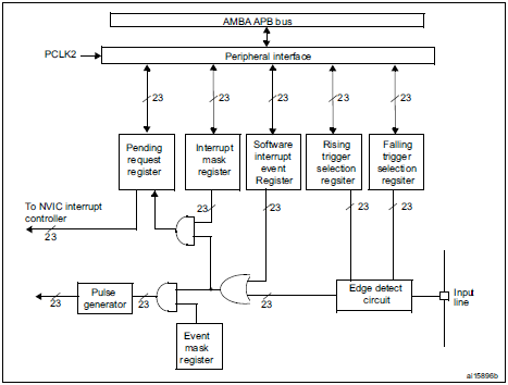
EXTI Block Diagram
……………………………………………………………………………………………………………………….
This example will show how to program a microcontroller to respond to the interrupt request caused by pressing a pushbutton connected to port E, bit 3.
In this simple example ports and controllers NVCI and EXTI are initialized first, and then infinite loop is executed. Here the content of the variable “IRQcount” is periodically written to the LCD. There is an interrupt function “EXTI3_IRQHandler« prepared. It is called upon pressing of the pushbutton and increments the value of variable “IRQcount”. Be aware that pressing of a pushbutton does not give a clean transition from logic zero to one. Due to the bouncing of the switch a series of pulses will most likely be present at the port causing a train of interrupts to increment the value of the variable “IRQcount” several times. Instead of pressing a pushbutton a square wave signal of appropriate amplitude can be connected to pin.
#include “stm32f4xx.h”
#include “LCD2x16.c”
int IRQcounter = 0; // declare & initialize IRQ counter
void main (void)
{
RCC->AHB1ENR |= 0x10; // Clock PortE
RCC->APB2ENR |= 0x00004000; // Clock SYSCFG – system configuration controller
GPIOE->MODER |= 0x55550000; // complete upper half of port E == outputs
LCD_init(); // init LCD
LCD_string(“Number of IRQs:”, 0x00); // display title string
NVIC_EnableIRQ(EXTI3_IRQn); // Enable IRQ for ext. signals, line EXTI3_IRQn
SYSCFG->EXTICR[0] = 0x4000; // select PE to make IRQ EXTI3
EXTI->RTSR |= 0x00000008; // allow positive edge interrupt for EXTI3
EXTI->IMR |= 0x00000008; // enable interrupt on EXTI3
while (1) {
LCD_uInt16(IRQcounter,0x40,1); // write IRQ count to LCD
LCD_uInt16(GPIOE->IDR & 0x3f,0x48,1); // write keycode to LCD
for (int i = 0; i<100000; i++) {}; // waste some time
} ;
}
// IRQ function
void EXTI3_IRQHandler (void)
{
IRQcounter++; // do the actual work
EXTI->PR = 0x0008; // clear interrupt flag for EXTI3
GPIOE->ODR |= 0x0100; // added to show the execution of IRQ function
GPIOE->ODR &= ~0x0100; // end of execution, about 300ns later
}
.
.
.
.
.
.
.
.
.
.
.
.
.
.
.
.
.
.
.
.
.
.
.
.
.
.
.
.
.
.
.


